Danube-type power transmission suspension & dead-end towers
The transmission towers can be categorized by the way they support the line conductors. In fact, the line grid is composed of transmission towers with different functions to ensure a safe support of the line conductors and to ensure a redundant power line guidance. Transmission towers can be classified as Suspension or Dead-end towers. Both types of the transmission towers (suspension and dead-end) studied in ANGELHY followed the geometry of Danube tower, a type of transmission tower widely used in Central Europe. Thus, the site of Annaberg-Buchholz was selected as a potential site of installation. It is located in Central-East Germany close to the borders with the Czech Republic.
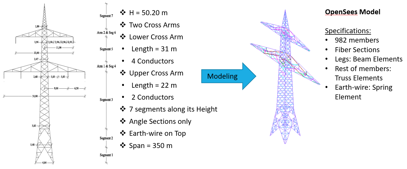
Suspension tower:A standard Danube tower is considered in the present case study. It has been designed according to the German National Annex of EN 50341-1:2012. The tower has a standard height of 50m and two cross-arms with different lengths. The lower cross-arm’s length is 31m while the upper’s is 22m. The main body of the tower has square cross-section (6.84m by 6.84m at the base) whose dimensions reduce with height. The tower members are made by hot-dip galvanised equal-leg angle profiles of various sizes. The tower is assumed to carry two 380 kV circuits each of them consisting of three phases. Each phase is made of a bundle of four conductors supported by a suspension insulator hanging vertically. Furthermore, a single earth-wire is installed on the top of the tower for lighting protection.
Dead-end tower:The Dead-End transmission tower of study has exactly the same geometry and is discretised in the same number of segments as the suspension tower. The tower carries two 380kV circuits, each of them consisting of three phases. Each phase is made of a bundle of four conductors supported by two insulators hanging horizontally. The type of insulators is assumed to be the same with those used in the suspension tower.